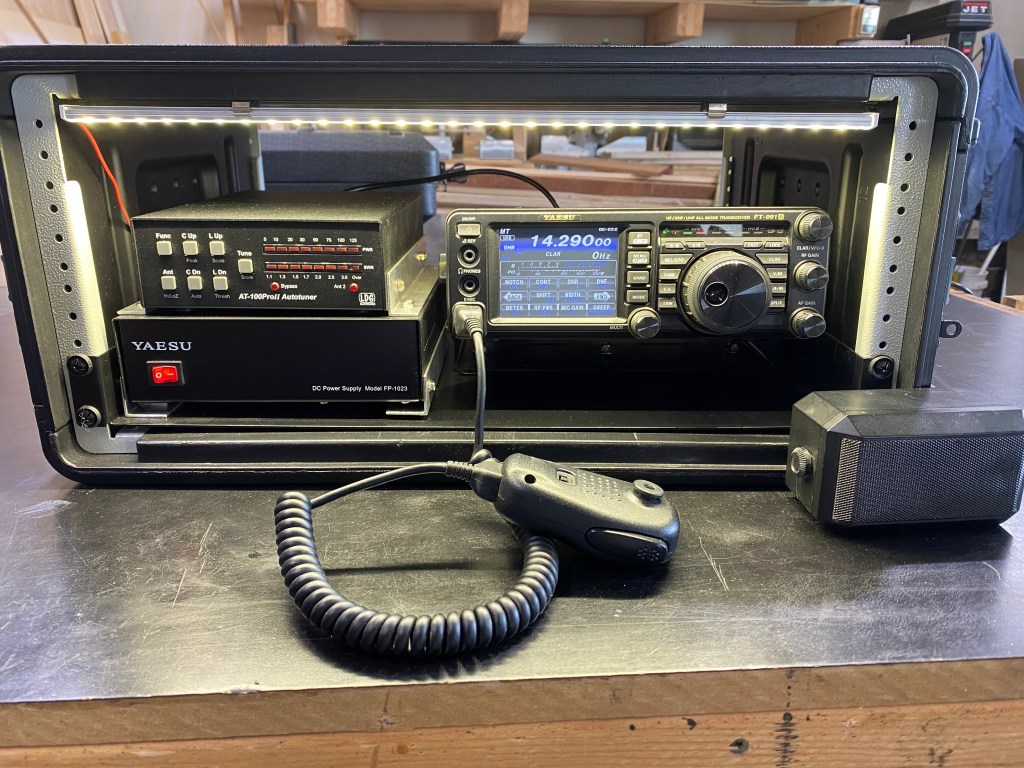
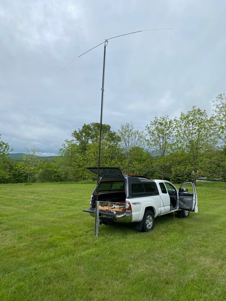
POTA SETUP
Make a plan:
•I wanted to use my Yeasu 991a transceiver (already own)
•Consider options of transport
•Suitcase setup
•Rackmount setup
•Rackmount case ($104)
https://a.co/d/4JOP6M8
•Tray to mount everything on ($21)
https://a.co/d/9a0Yg01
•Power Supply Yaesu FP-1023
•HRO ($140)
•Antenna Tuner LDG AT100PRO-II
•Power meter and SWR meter built in
•HRO (LDG, AT-100PRO-II, Antenna Tuners Automatic, AT100PROII ($270)
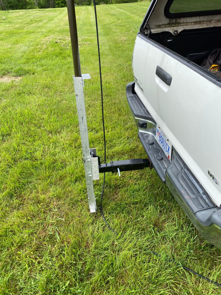
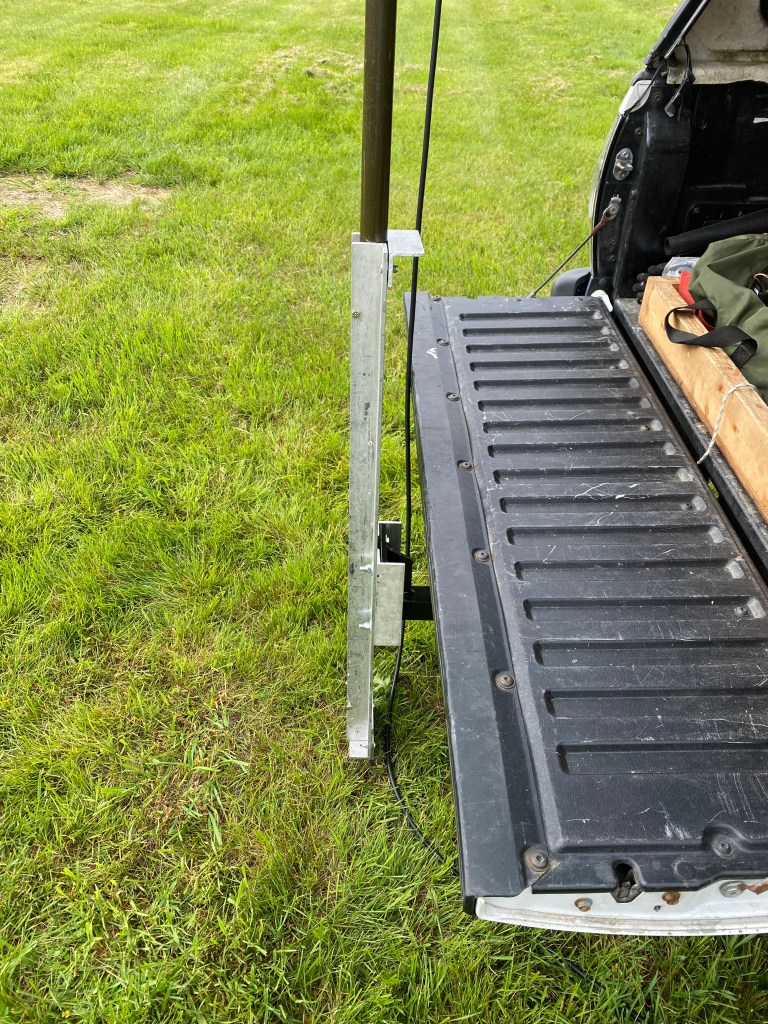
•Mobil Mounting Bracket ($50)
•https://a.co/d/ezYRG4d
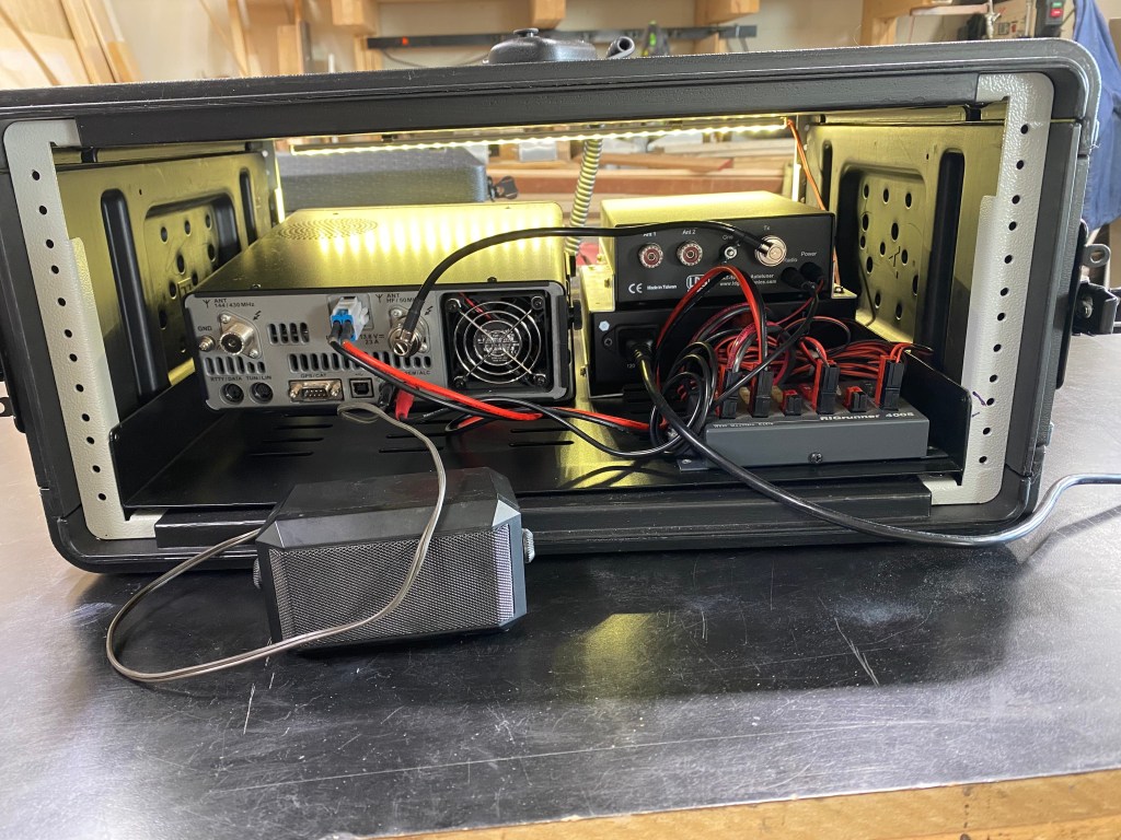
•Power Distribution Rigrunner 4005 ($95 I had)
•West Mountain, RR/4005/C 58312-1038, DC Power Panels, RR/4005/C 583121038
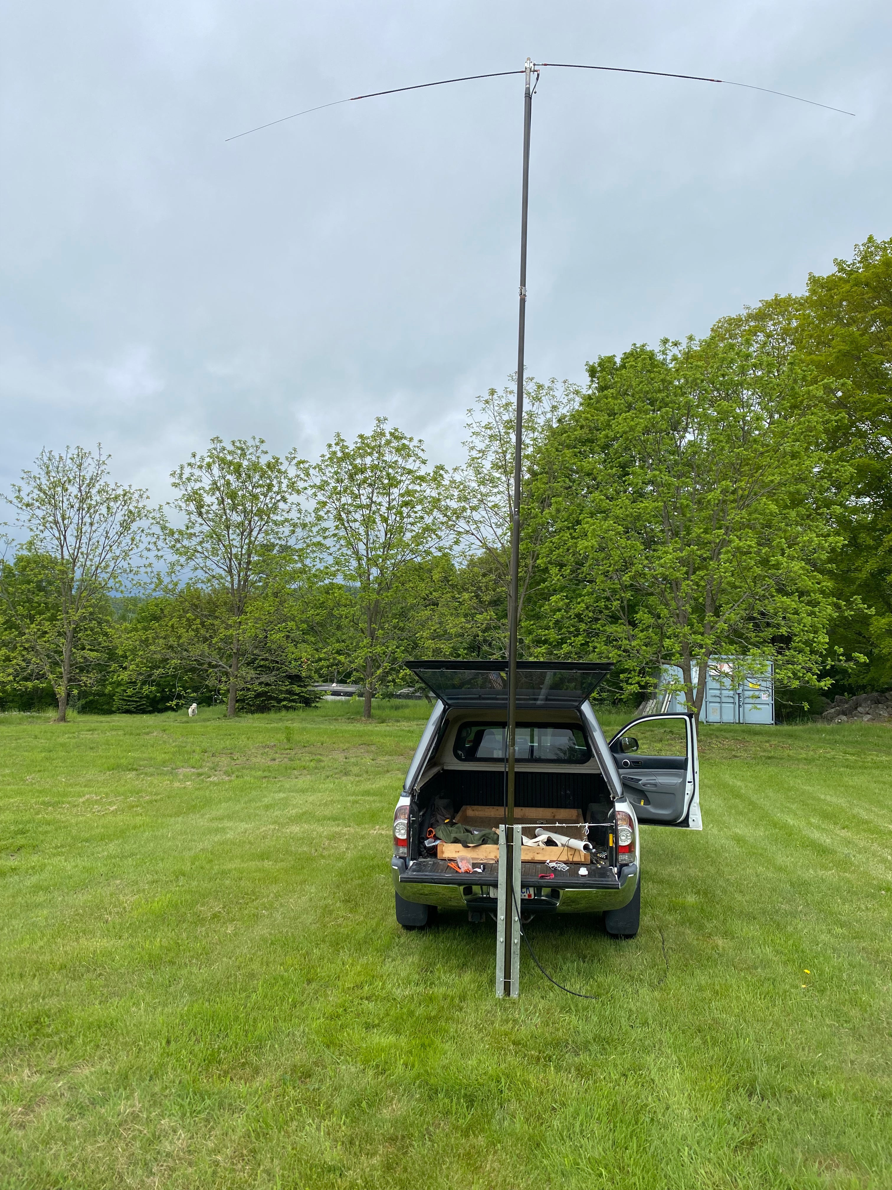
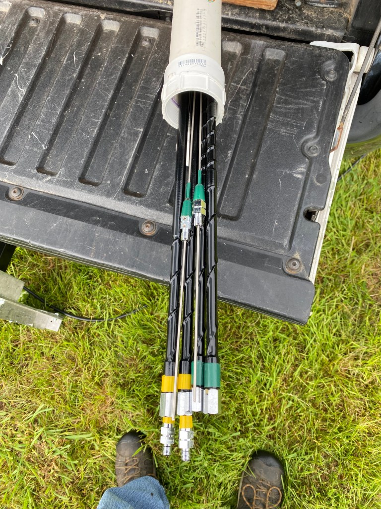
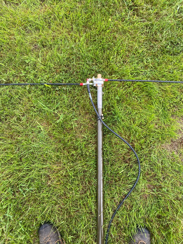
•Antenna Ham Sticks
•600W 40M/20M/15M 2 each ($40 each)
•250W ($23)
•Ham Stick to Dipole ($25)
•https://www.hamradio.com/detail.cfm?pid=H0-019257
•A better antenna would be a BuddiHEX ($750)
•BuddiHEX™
•20M to 6M
•1.5 KW
•10 lbs 10’ across
Solar Project
Make a plan
•Phase 1
•I want my Power Supply to have a battery backup
•The Power Supply should keep the battery charged
•Phase 2
•I want to add solar panels to charge the battery when the power supply is off
•End result I don’t need the power supply on while operating
The MATH
•Radio runs off 11 to 15 VDC
•Radio draws 4A – 22A amps when transmitting 100W
•PAN Display Unit draws 1.2 amps
•12V lights / HAM Clock Draws / RF Tuner
•draw 1.7 amps
•So that’s ~25amps
Batteries
•Understanding battery power
•100Ah is 1 amp draw for 100 hours roughly
•Or another way 12V * 100A = 1,200W
•So, if we are drawing 25 amps,
•But it’s not 100% of the time
•Mostly we are drawing like 5 amps
•25/75% TX/RX (for this example)
•6.25 + 3.75 = 10 amp in an hour
•Battery will last approx. 10 hours
All Batteries are not the same!
•Lead Acid Batteries
•Safety first DON’T use Flooded batteries
•They could vent hydrogen gas inside the shack
•Don’t use and old battery you have in the back of the garage
•GEL sealed batteries
•Absorbed Glass Mat (AGM)
•Have fewer charge/discharge cycles
•It’s lighter
•It’s less expensive
•1 year warranty
•Neither of these styles of batteries can be fully discharged without decreasing the capacity or will die all together.
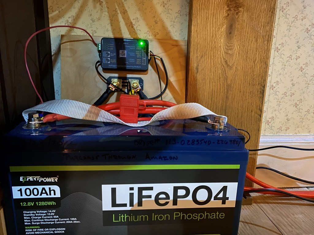
•LiFePO4 Lithium Batteries
•MUCH lighter (27lbs).
•Will last 10 years (cheaper ones will have 5 year warranty)
•Has a built in Battery Management System (BMS)
•Controls
•Over charging
•Over discharging
•HUGE advantage because you don’t have to worry about discharging it to the point you destroy the battery.
• Automatically balances the individual cells,
•Protects against short circuits
•Senses the temperature of discharge and charging
•CON can’t be charged below 32° or purchase the more expensive battery that you can charge under 32°
•If I had it to do again, I would buy a 200Ah battery rather than putting 1 100Ah battery and thinking of adding on later, because you can’t add more batteries after 6 months.
Critical part of this plan
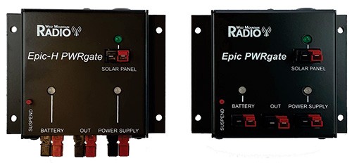
•Epic PWRgate by Western Mountain Radio
•Has Power Supply Input
•Has Battery Input
•Has a 40a output
•Has a Solar input
•Has a USB port
•EPIC-H ($189.95)
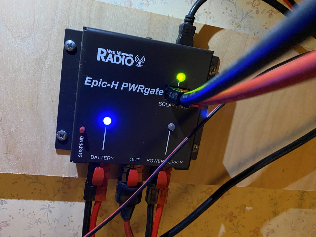
EPIC PWRgate details
•Provides 40amps of power
•Power Supply
•Battery
•Automatically switches from power supply to battery if commercial power loss or Power Supply fails
•Supports Lead Acid (GEL/AGM) and Li-ion (LiPO4)
•Charge the battery with 10amps
•Supports Solar panels directly <=30V
•Has MPPT built in
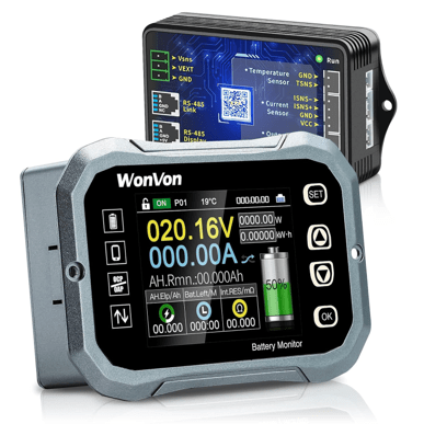
Battery monitor device
•WonVon 100A monitor
•2 parts the Display and the Electronics
•Measures battery
•Charging current
•Discharging current
•Percent left in the battery
•I tried a cheaper version
•Got very poor results
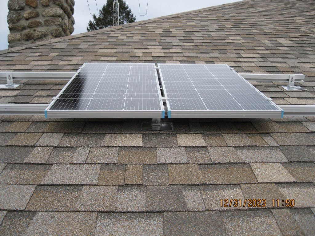
Solar Panels
•Solar panels you’re looking for are without the micro inverter.
•Pick the Monocrystalline solar panels
•They are more efficient than the polycrystalline panes
•Only Pick Grade A
•Grade B can be new but damaged (internally) but it does meet specifications
•Grade C damaged and does not meet Specifications
•Renogy 100W
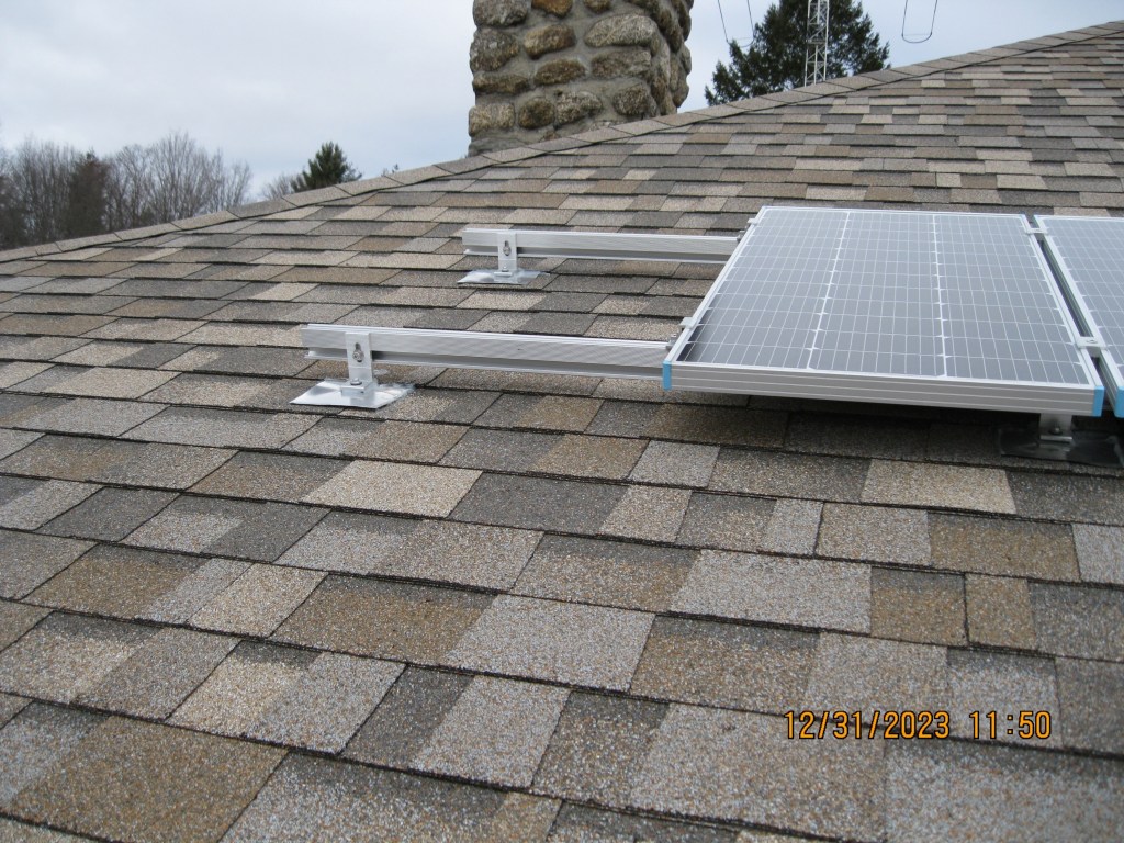
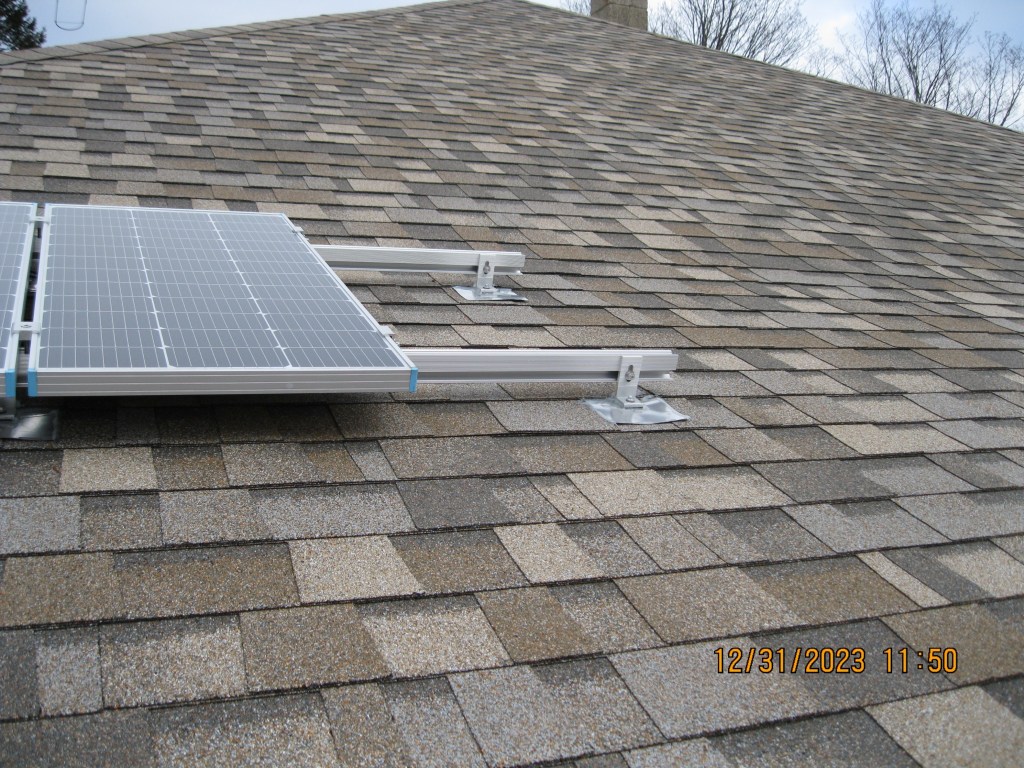
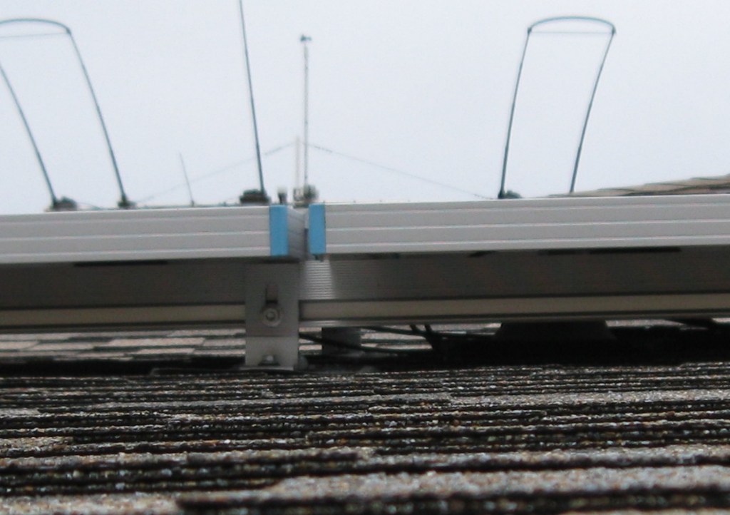
Mounting Solar Panels
•Don’t mount directly to the Asphalt Shingles
•Cables are not to touch the shingles
•Screws (big screws) into your joist, that will give you strength for wind and snow load
•Use RTV sealant into the holes before you screw down the frame
•Use aluminum to be inserted under the shingle above
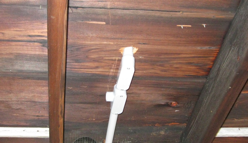
•Use a boot for the conduit penetration point
How to wire up the Solar Panels
•These panels nominally output 20V, well that would fry my battery.
•That’s where the PWRgate charge controller comes in, it will provide the proper voltage to the batteries.
•Don’t ever feed the PWRgate from another solar charge controller.
•I took the two 100W panels and connected them in parallel down to the PWRgate (12V)
•They make special Solar Panel cables 10ga with double insulation
•Frame must be grounded
Peak Sun Hours
•https://footprinthero.com/peak-sun-hours-calculator
•My zipcode, angle of panels, direction of panels
•My monthly averages:
•January: 3.49 * 200W = 698W
•February: 4.79 * 200W = 958W
•March: 5.4 * 200W = 1,080W
•April: 5.48 * 200W = 1,096W
•May: 5.39 * 200W = 1,078W
•June: 5.61 * 200W = 1,122W
•July: 6.11 * 200W = 1,222W
•August: 5.96 * 200W = 1,192W
•September: 5.48 * 200W = 1,096W
•October: 4.03 * 200W = 806W
•November: 3.28 * 200W = 656W
•December: 3.06 * 200W = 612W
Peak Sun Hours
•Previous example is if you have sunup to sundown sun
•If you don’t have sunup to sundown
•Not to worry peak is near noon
•Just getting an hour before to an hour after noon will provide you a lot of charging
•You could consider a directional system that tracks the sun to get maximum solar power
Generators
•There’s
•Generators
•Whole house Generators
•Inverters run by Battery
•Generator/Inverters
•What you’ll need
•240VAC to run your well
•Calculate total power to run your appliances
The Generator
•The cheapest are generators
•They run at a set RPM in order to achieve the 60Hz
•There very poor on gas consumption
•Most put out a modified a waveform
•Gas generators that are not run for long periods the fuel will turn to varnish
Whole House Generator
•The most expensive method
•They still run at a set RPM in order to achieve the 60Hz
•Whole house generators run off propane, so the carburetor won’t foul,
•Most whole house generator are fuel injected.
•These mostly have a pure Sine Waveform
•They include an automatic switchover
Inverters run from Battery
•One more key item is that there are generators/inverters that only provide 120VAC
•This will not provide power to 240vac appliances, like your well
You’ll need a generator that is capable of 240VAC. Is there a way to cut corners instead of a whole house setup which is expensive? Yes, buy a good generator (fuel injected after all your saving $$ compared to the whole house system) and then install a generator panel.
Generator Inverters
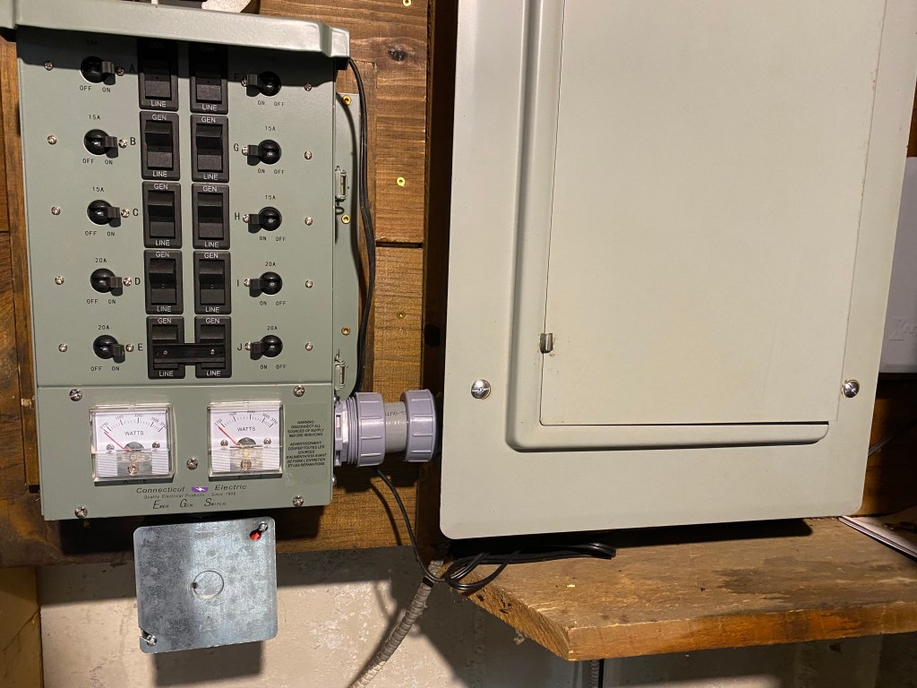
Well, the inverter generator does not work this way it practically runs at an idle until the load increases and then the motor will increase in RPM. Also, the power coming out is perfect clean 60Hz. Another note is that most generators have a carburetor. This takes the generator power output to your emergency circuit breaker panel and provides power to 8 or 10 circuits. You choose the critical circuits but (don’t forget the shack like I did) and when you have a power outage. Start the generator then go to this panel and start turning on the critical circuits. Caution: anything that runs off 230VAC requires two of those precious circuits, so my well requires two of the 10 circuits. MY setup is a Honda EU7000is inverter. They have Bluetooth capability; it tells you me when the gas is about to run out. The generator panel downstairs is a Connecticut electric, easy to install yourself. Determine which circuit breakers in your current panel run the critical circuits. Then you’ll need to turn off the power to your whole panel and now remove the panel cover. Remove the wire coming out of the circuit breaker and using the wire pair from the generator panel wire nut one and then install the other into the circuit breaker. This inserts the generator panel into the path for that circuit. This way you can break the power (or in this case lack of) from the street and connect the generator power. Do this for all the critical circuits. You now have control over what the generator feeds, in case your generator is not big enough to run everything at once.
Emergency Circuit breaker Panel
•This makes the standalone generator much more reliable
•This takes the generator power output to your emergency circuit breaker panel and provides power to 8 or 10 circuits.
You choose the critical circuits but (don’t forget the shack like I did) and when you have a power outage.
Start the generator then go to this panel and start turning on the critical circuits.
Caution: anything that runs off 230VAC requires two of those precious circuits, so my well requires two of the 10 circuits.
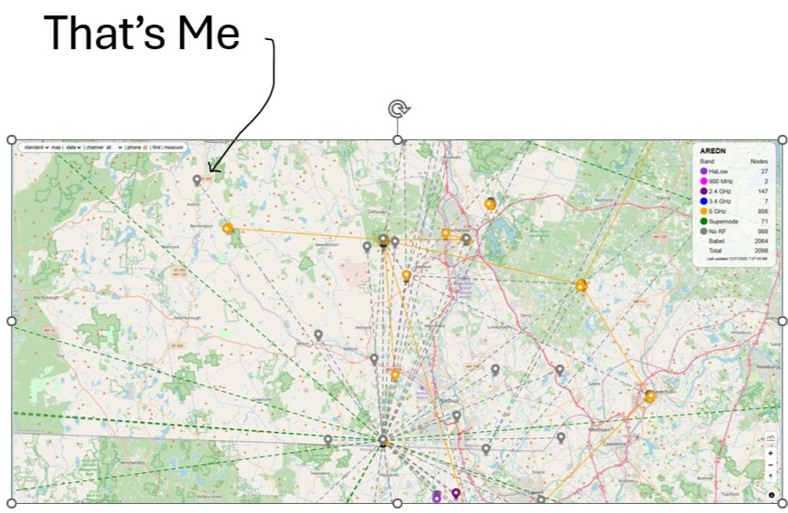
AREDN
Amateur Radio Emergency Digital Network
•First what can you do with AREDN?
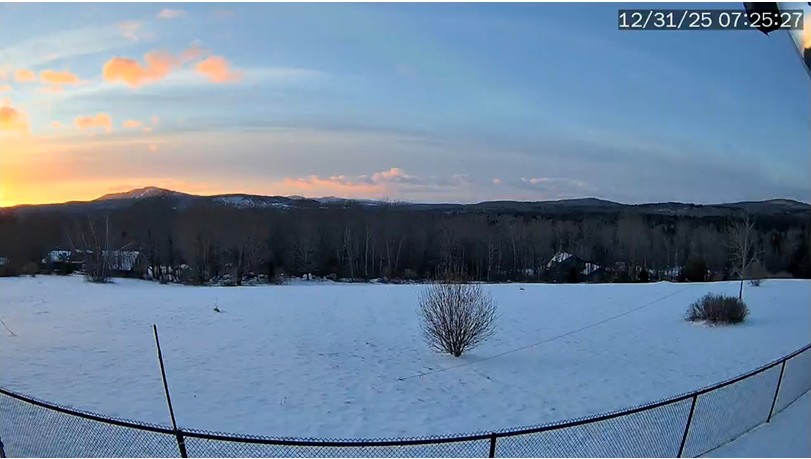
•Share your view with a camera live
•Requires an account for security reasons
•Fred’s AREDN backbone has AI camera capability
•Share your weather
•Share your Flight tracker live feed ($37)
•DMR repeaters / ARPS
•VoIP phones / Video Conferencing
•Mesh Chat
•Email (WinLink/Open Email/Citadel)
•File sharing / WEB Services
•Networking tools
•And more to come
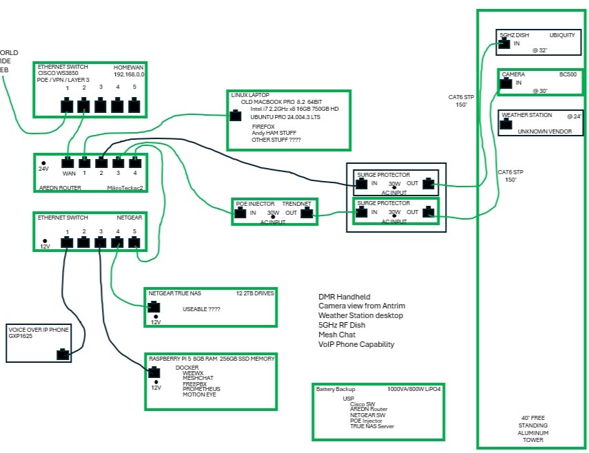
MAKE A PLAN
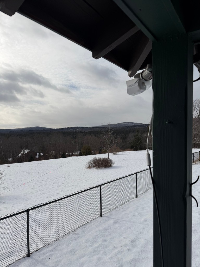
•I wanted to share my view with a camera ($300)
•I want to share my weather station and my crazy wind speeds (~$300-600)
•I want to get a VoIP Phone (~$35)
•I’d like to get a 5GHz Disk to access the AREDN net directly (~$300)
How to Start
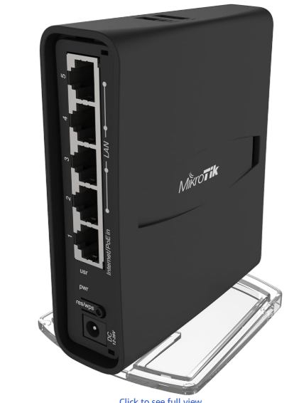
•To start with, you’ll need a router
•MikroRik hAP ac2 ($70)
•Amazon.com: MikroTik hAP ac2 RBD52G-5HacD2HnD-TC Dual-Concurrent 2.4/5GHz Access Point, 802.11a/b/g/n/ac, 5 x Gigabit Ethernet ports : Electronics
•
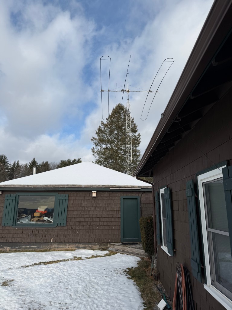

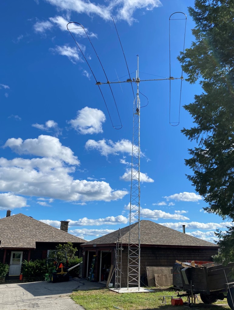
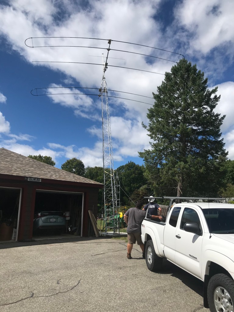
My Experience with Installing a Tower and New Antenna
It started over 2 years a go when my wife and I decided to down size and chose a home for us to spend our final years enjoying. I was also looking for a home that had a view and that would allow a ham radio tower.
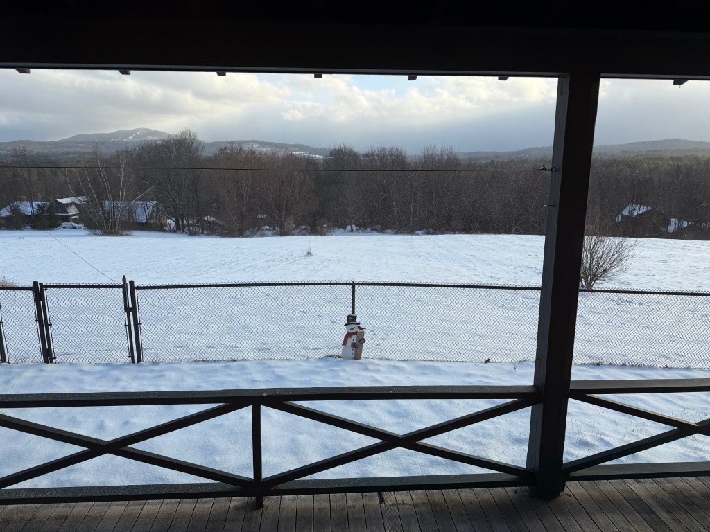
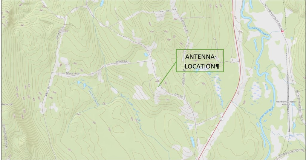
My property & home
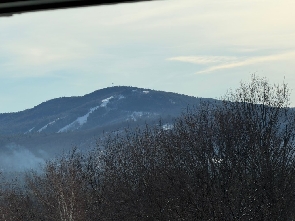
My house is at 810’ above sea level. To the north and east the tree line is about 100’ away and the ground slopes away about 40’ down north and 100’ slope down to the east. To the west is nothing for 300 yards and slopes down over 100’. To the south there is 300 yards to the tree line below which is below line of sight. Otherwise we can see 75 miles south and 2 miles west and east. To date as a weather front comes through, we have experienced winds at around 45MPH. You can see from the photo that the view is great.
Antenna selection
One of the first things I was told about selecting an antenna was wait until you could afford a SteppIR antenna. It made sense because you don’t not have to worry about VSWR because the antenna is changing the element length to match the frequency currently tuned to. I have a Stepp BigIR Mark IV vertical. 40M – 6M. This antenna works great for FT8. Just need to make sure you have lots of ground radials. I have 32 40’ radials.
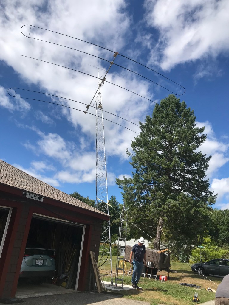
I narrowed my selection to the SetppIR DB18 antenna. I was looking for something that would provide good results for low sun cycle propagation. That meant wanting 20M and 40M, sure the other bands would be nice when the sun cycles improved. I focused on 3 element vs 4 elements could not justify a $2000 increase for an antenna that gave less than 2db more gain. So, I settled on the SteppIR DB18.
- Antenna is a SteppIR DB18 7MHz to 50MHz
- 10.1 sqft wind load
- 96lbs
- SDA2000
- Rotator is a Alfa Spid Big RAK
- 1’ wind load, 3,240 in lbs turning torque, 14,000 lbs braking torque
- 16lbs, 2” top to 2.6” bottom.
- Hold >700 lbs.
- Mast ¼” thick walls 17’ long 2” an the base and 1 ½” at the top. 1.5 foot wind load buried 4 feet into the tower
Town requirements
Some towns allow amateur radio tower to 50’ other towns 70’. Antrim initially had a 70’ for amateur radio and if you wanted taller then you had to follow the commercial tower requirements. It is now whatever the FCC / State requires. When I filed for the permit the inspector stated that there is not building permit required for amateur radio tower but he did look at the request to ensure there was no safety issues (could the tower fall on a neighbor’s house, public roadway.) and that I was more than 50’ from the roadway and 25’ for the property line. I had also submitted a copy of my Amateur Radio License, which he thanked me for that and requested that I submit my renewal when I do 10yr renewal. He then filed all of it into the town records.
It doesn’t hurt to talk to your neighbors to ensure that they will not be pissed at you for putting up this (non-HAM’s) ugly tower. I did this and we agreed that if I put the tower towards the front of my garage it would not be as visible to him.
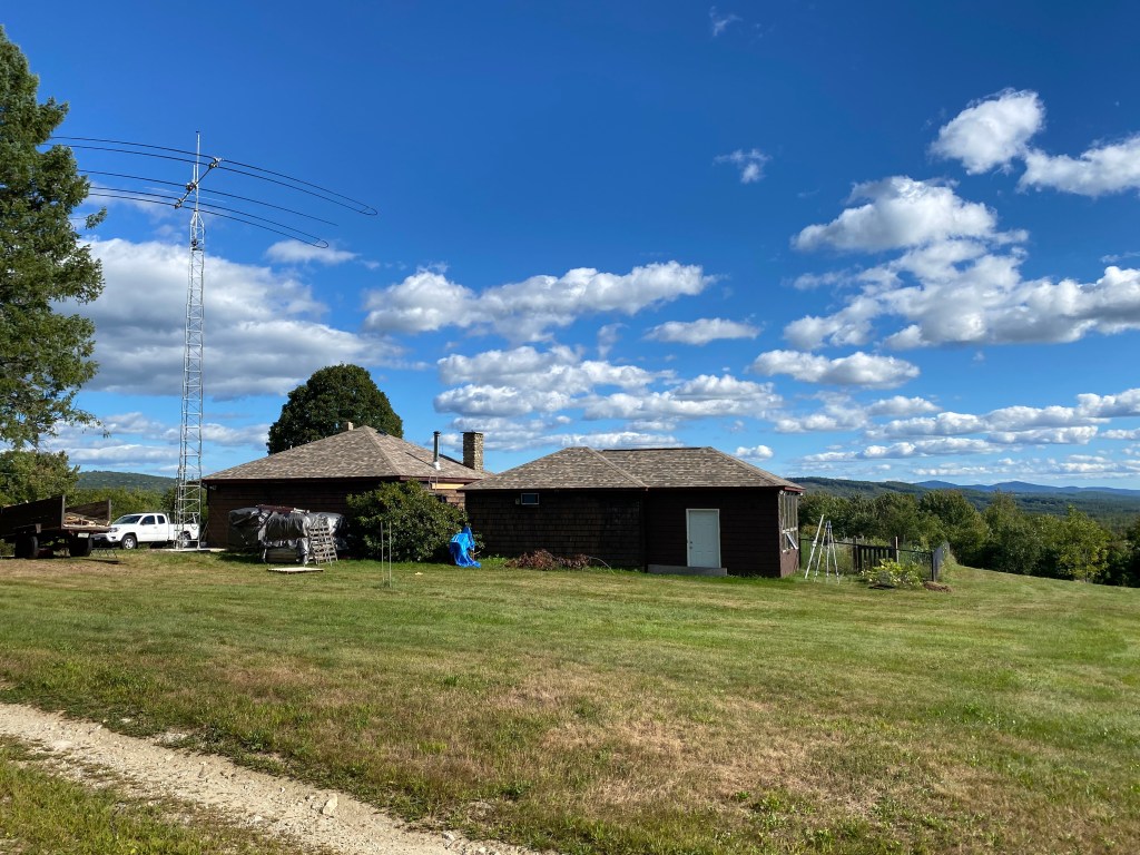
My Tower requirements
So, to start with you have to have a wish list in mind. Mind were as follows:
- DYI (do it yourself) Install
- No climbing
- Fold Over at the base
- Would be nice to be able to hang a 80m inverted Vee (65’)
Tower selection
Easiest way was to start looking at Rohm catelog, they have a section in front to get you started. They start with understanding TIA-222 revision G. It goes through Classification of the antenna structure, HAM’s will always be Class I. Next is the EPA (Effective Projected Area) or area (size) of your antenna, don’t forget the mast and the rotor. Next is what is your exposure, folks in the flat lands of Ohio(?) will be exposure C, here in New Hampshire where we have mostly 100’ trees around most home we will be Exposure B. Anyone living along the coast fit the last exposure D. So the next category is what snagged me. Topographic category. I got snagged as a category 3 site, at the top of a hill which means you must multiple the wind load by 2.3. Dam that’s 10.1 + 1 + 1.5 = 12.6 * 2.3 = 28.98. That’s a huge value.
So now is the search for an antenna company to meet my wish list. Remember, I’m not interested in climbing a tower. Lots of towers out there but I needed something with the ability to handle 29 EPA (that’s TIA-222 talk for wind load). ROHM towers did not meet my wish list of no climbing towers. Universal towers has a tower rated for 35sqft at 110MPH winds. Next was Heights Towers, they had towers rated by exposure that would meet the requirements. I love the features that they offer, the fold over kit. But not the cost. I’m retired and not made of money, so I opted for Universals tower. When looking at these towers don’t forget the cost to ship it to you. Big difference from Florida to NH vs Michigan to NH (more than double).
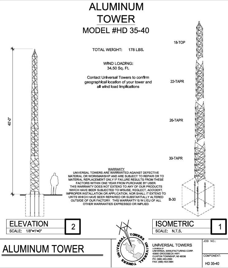
Tower height
I read in QST “The DR Is In” article where someone was asking how high does a Yagi antenna need to be? His reply was a Yagi only needs to be 43 feet off the ground. I also know that angle is related to the topology of where the tower is installed. So my 40 foot tower is great for my topology.
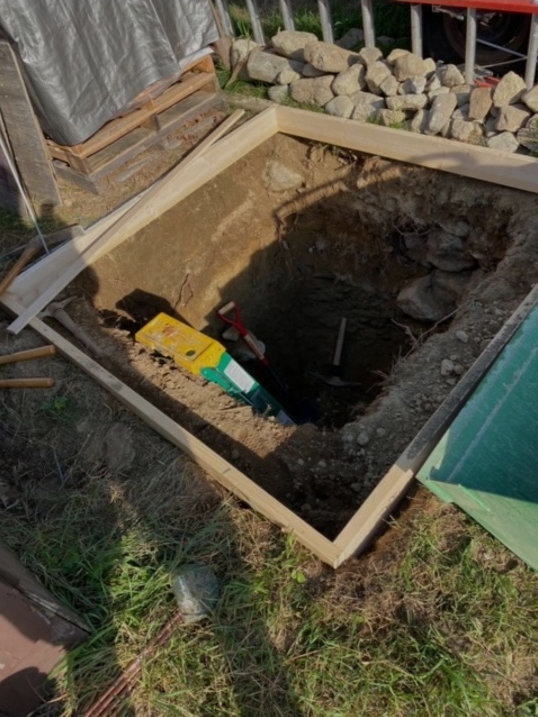
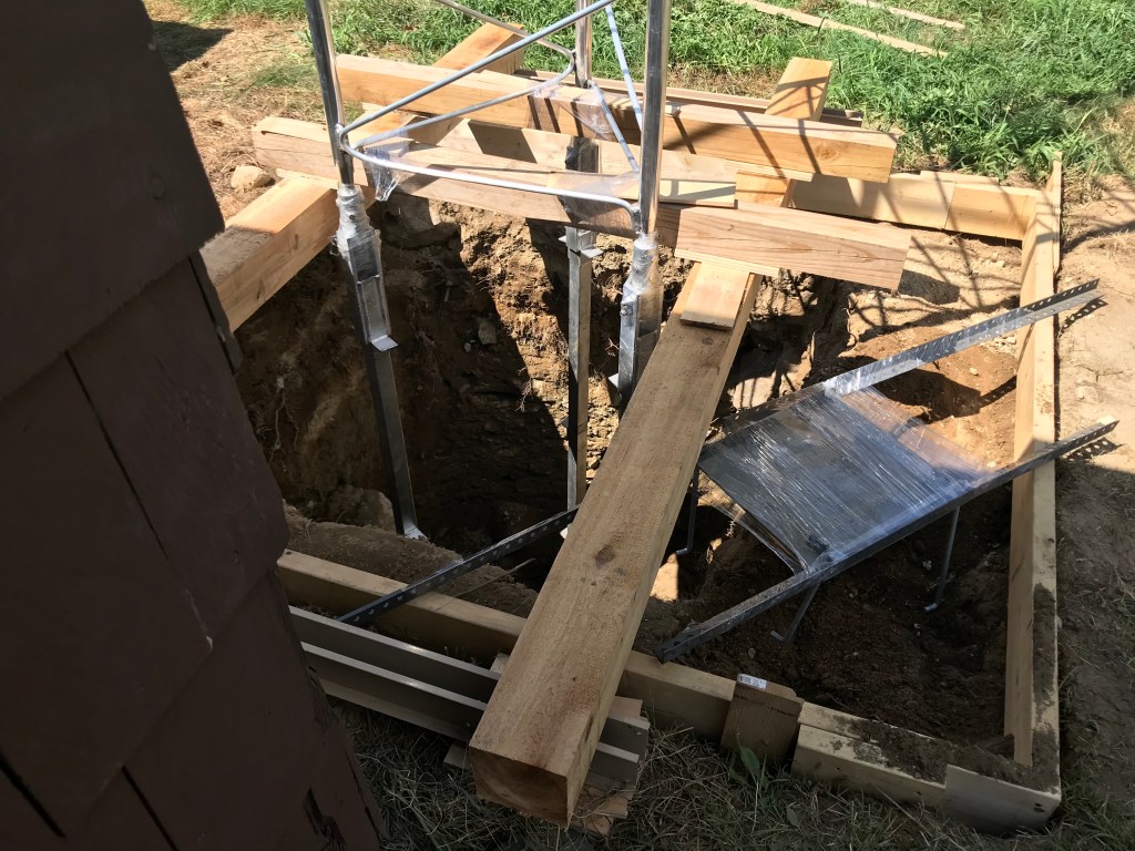
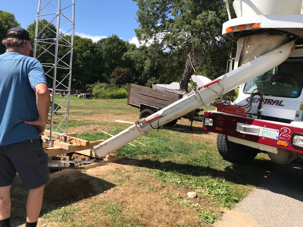
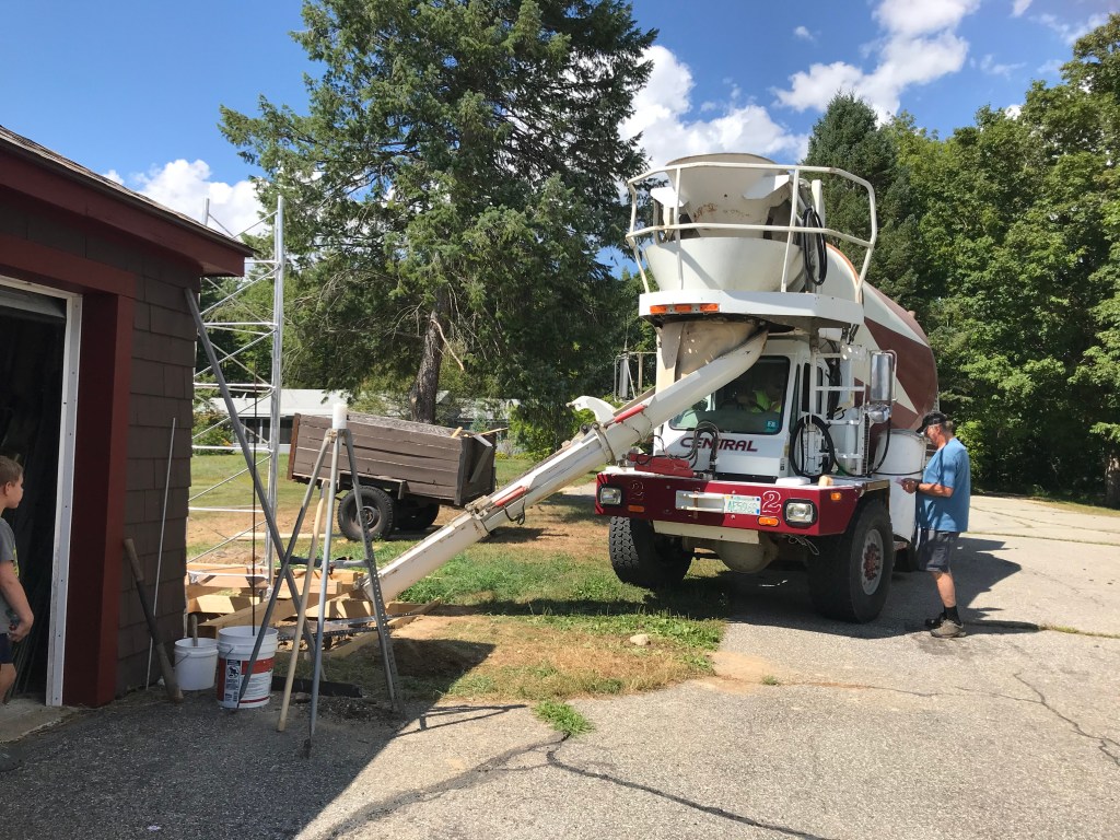
Did you know that digging a hole for a self-supporting tower is a really big hole. 5 feet by 5 feet by 6 feet down. Took me 2 weeks couple hours a day. Last foot was this stone and stone dust mixture only got a couple inches a day. Making the hole 5’ by 5’ at the bottom was no fun, cause now every shovel full is going up over 6’. I moved my dirt away ever day. Why not a backhoe? They don’t want the dirt disturbed around the hole. Besides I wanted to DYI. It takes 6 cubic yards of cement to fill a 5’ x 5’ x 6’ deep hole. I waited almost 2 weeks (actually built the antenna) to raise the tower/antenna. Concrete was nice and hardened. Lessons learned, concrete in the center will shrink, next tower (HaHa) don’t level, instead have the center higher than sides and exaggerate it.
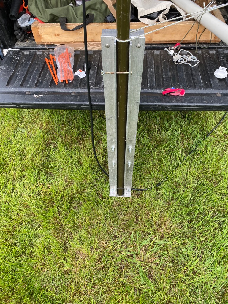
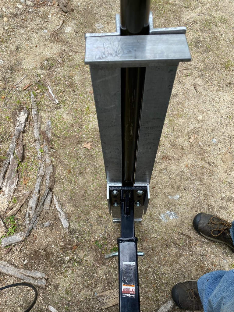
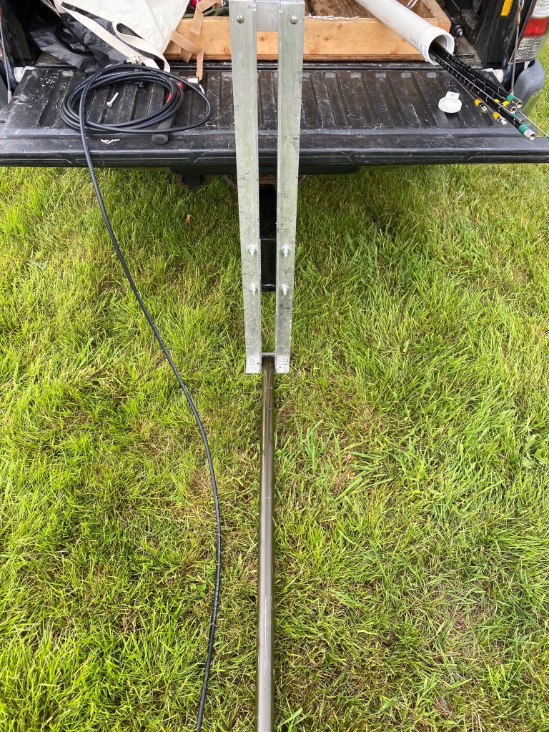
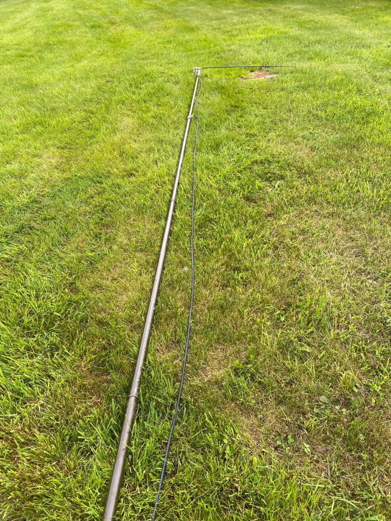
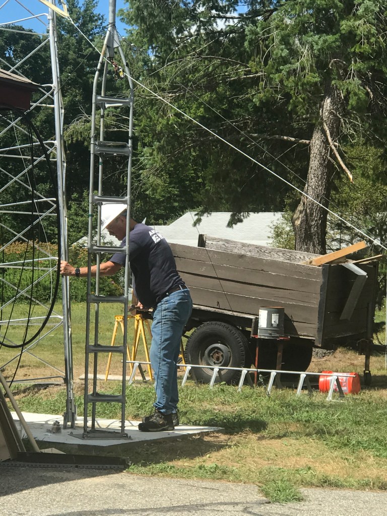
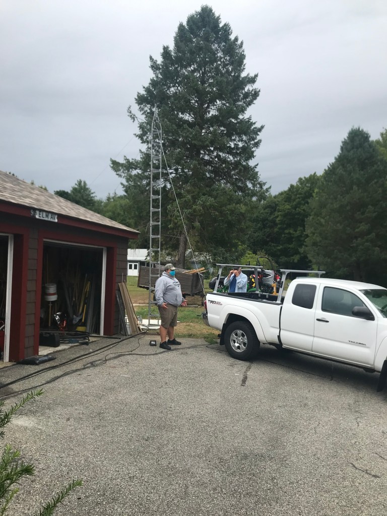
Tower raising
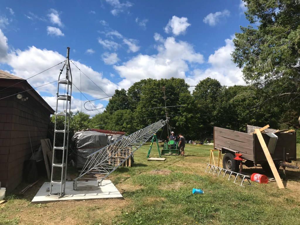
So, I had some older tower parts and I though I’d use this as a fulcrum. On the back of the truck is a hand winch. Went high enough on the tower (half way to the top of the actual tower) to anchor onto the back 2 legs. The fulcrum didn’t respond well so I called a safety assent time out. We lowered and only went up about 12’ and only used a 10’ section of tower. This ended up working much better but not as good as I’d like. I’d also like to swap out the hand winch with a power winch.
Cable selection
I choose to use LMR900 to run from the entry point to the top of the tower. Worked out to be 110’. The top of the tower to the antenna is 10 feet of LMR400, from the house entry point to the back of the radio is 15’ LMR400. Ever wanted to know how much power you are radiating in the direction of your wonderful Yagi? First you have to determine the power you’re going to lose through the cable at the frequency you’re transmitting at. Next subtract from the power out of your transmitter out power, say 100 watts. Then look up your antenna gain, convert dbi to db and multiply that by how much power you are providing the antenna at that frequency. The results will be how much transmit power you are sending in a direction. This whole exercise is based of db and transmit power or db loss / gain. I had to convert things back and forth to get the right power from db gain.
| Frequency | BAND | Cable loss @ frequency | Watts – db loss of cable | Antenna Dbi gain from manufacture | Antenna gain in db (dbi -2.15) | Ant Output in watts |
| 100 | ||||||
| 7.2 | 40M | -0.23657 | 94.69838 | 6.2 | 4.05 | 240.6 |
| 10 | 30M | -0.27917 | 93.7741 | 5.4 | 3.25 | 198.2 |
| 14.225 | 20M | -0.33352 | 92.60795 | 7.4 | 5.25 | 310.2 |
| 18.13 | 17M | -0.37702 | 91.68491 | 8.3 | 6.15 | 377.8 |
| 21.3 | 15M | -0.40905 | 91.01118 | 8.5 | 6.35 | 392.7 |
| 24.95 | 12M | -0.44317 | 90.29896 | 8.8 | 6.65 | 417.5 |
| 28.8 | 10M | -0.47662 | 89.60619 | 9 | 6.85 | 433.8 |
Grounded the tower on all three legs. Used 4 gage bare solid copper from tower leg to ground rods, 4’ from tower leg. I wanted to run the cable down the center of the tower. It made sense that lightning would travel on skin effect (tower legs) and not on the RF/control cables to ground. I did not have a good enough method to hold the cable suspended in the center of the tower. A failure of my ingenuity.
Also, at the entry point into the house there is a ground rod that I have a RF lightning arrester attached to. There are no lightning arrestors for the control cables. This ground rod is also grounded to the point of entry ground rod. And is the ground for all of my radio and support equipment.
At the very top of the tower I have a wind gage (anemometer) doesn’t give me the wind direction. It’s a very simple device. It uses a bicycle reader and the anemometer at the top. Just counts revolutions, gives you and average and MAX. All I needed, I’ve tried others and they didn’t last very long or did not give an accurate wind speed.
So far I’m getting great reception into Europe. Had contacts with Japan, South Africa and have been hearing Australia and Indonesia. One of the reasons I love FT8 is it labels the contacts country of origin. Just wait as the sun cycle improves so will my contact log.
Next project is to complete a wiring diagram of my shack. I’d like to be able to visually know how everything is wired together.


I’m very sad that SteppIR has decided to stop making antennas for amateur radio enthusiasts.
